Hey there, fellow cable assembly crew—whether you’re a design engineer, a quality control tech, or a buyer who’s ever stared at a spec sheet and thought, “Wait, what even is insulation resistance, and why does it matter?” If you’ve been part of the cable game for more than five minutes, you know that skipping a critical test here can lead to some real headaches down the line. Last quarter, we had a client reach out panicking because their custom cable assemblies kept failing in-field—turns out their insulation resistance wasn’t up to snuff, and moisture had creeped into the jacket, causing short circuits. That’s exactly why today I’m breaking down how we test insulation resistance on every cable assembly that leaves our shop, no jargon, no fluff, just real-world tips we’ve picked up over the years. Cable Assemblies & Accessories
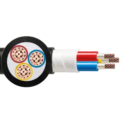
First off, let’s keep this super basic: insulation resistance (IR) is the measure of how well a cable’s insulating material stops electricity from leaking from the conductor inside to the outside world—like moisture, other conductors, or whatever’s around it. If that number’s too low, you’ve got a problem. Think about it: our customers make stuff from medical devices that go inside patients to industrial robots lifting heavy parts around factories. A bad IR reading means downtime, safety risks, even compliance fails. That’s why this isn’t a “nice-to-have” test—it’s non-negotiable for every assembly we build here.
Before we jump into the actual test steps, there are a few pre-checks you can’t skip. I see too many techs rush this part and mess up the whole test. First, you gotta make sure the cable isn’t just off a fresh production run—no, wait, even if it is, let it sit at ambient room temperature (between 15°C and 35°C, if you wanna get specific) and 45-75% relative humidity for at least 2 hours. Why? Because if the cable was just wound tight on a spool or sitting in a hot box, the insulation molecules are stressed, and you’ll get a wonky reading. Second, inspect the assembly for any obvious flaws—scratches on the jacket, nicked conductors, dirt or oil on the ends. Even a tiny scratch that exposes a sliver of conductor will tank your IR, so fix that before you even pick up the tester. Last, make sure you’re using the right tester. We only use megohmmeters (aka meggers) with a range that fits our cables—for low-voltage assemblies (under 1kV), we use a 500V megger, and for higher voltage stuff, 1000V. Don’t use a regular multimeter here; they’re not designed to measure high resistance (insulation resistance is usually in megohms, not ohms) and you’ll get garbage data.
Now, the step-by-step test. Let’s say we’re testing a 2-meter long USB-C to power cable, or a custom industrial harness with multiple conductors—same basic process, just scale up for multi-conductor assemblies. First, prep the test leads. Every megger has two main leads: a line lead and an earth lead. Some have a third, guard lead, which is super helpful for keeping surface leakage off your reading. Speaking of surface leakage—if the ends of the cable are dirty, water or oil on the connector pins, that’s a big one. Wipe down the connector ends and the exposed insulation with isopropyl alcohol and a lint-free cloth before you start. No exceptions. Next, set the megger correctly. Double-check the voltage setting—we always match the cable’s rated voltage. If a cable is rated for 30V DC, 500V is the right test voltage; going higher can damage the insulation, going lower gives a less accurate reading. Set the timer too—most meggers have a 60-second hold setting. Insulation resistance has what’s called an absorption coefficient—you wait 15 seconds and 60 seconds, then divide the two. For most good cables, that ratio should be at least 1.5, which tells you the insulation is solid. Rushing the test and taking a 10-second reading? Waste of time.
Now, connecting the leads. For a simple single-conductor cable, it’s easy: clip the line lead to the exposed conductor, and the earth lead to the outer insulation (or even better, wrap a piece of tin foil around the insulation about 1 inch back from the end—touch the earth lead to the foil, not the bare jacket, to make a tight, consistent connection). For multi-conductor assemblies, like a 5-conductor signal cable, we do two types of tests: conductor-to-conductor and conductor-to-shield. For conductor-to-conductor, pick one conductor as line, another as earth, and the guard lead to the insulation around both. That stops any leakage between the two conductors’ insulation from messing up the reading. For conductor-to-shield, same deal: line on a conductor, earth on the shield, guard on the insulation between them. And if there’s a drain wire? Oh, that’s part of the shield—clip the earth lead to the drain too, just make sure it’s a solid connection.
Wait, the guard lead is a game-changer I wish more people used. Last month, we had a test that kept reading 100kΩ on a cable that should have been 10,000MΩ. Turned out, a tiny puddle of water on the test bench was causing surface leakage. We hooked up the guard lead to wipe that surface leakage away, and the reading jumped to where it should be. No more wasting time blaming the cable for a dirty bench. That’s the kind of small trick that makes this test worth doing right.
Once everything’s connected, hit the test button and hold for 60 seconds. Jot down that number, then maybe do a repeat test on another section of the cable, just to make sure it’s consistent. If the reading is below the manufacturer’s spec—usually, for low-voltage cables, it’s 100MΩ per 1000V of test voltage, so for 500V, that’s 50MΩ—you’ve got a problem. Now, before you toss the cable, troubleshoot. Did you leave the test leads touching bare metal? Double-check connections. Is the cable too cold or too hot? Wait for it to acclimate. Did you get moisture inside the connector? Sometimes you can bake the assembly in a low-temperature oven (around 60°C for 4 hours) to drive out moisture and retest. If it’s still below spec, time to flag that cable as non-conforming.
Now, let’s talk about real-world examples, because numbers are great, but what does this look like for our clients? Last year, we made a set of custom cables for a agricultural drone company. Their cables needed to withstand dust, rain, and temperature swings from -20°C to 60°C. We tested IR on every single one before shipping—they all checked out at over 1,000MΩ at 500V. When they installed them, they had zero short issues, even after 6 months of field testing their drones in the Midwest rain. Contrast that with another client who skipped testing and ordered off a cheap supplier: their cables were coming in at 20MΩ, which is barely over the minimum spec. A few weeks in, their equipment started glitching because of leakage, costing them thousands in downtime. That’s exactly why we don’t cut corners here.
A few quick mistakes we see all the time, so I’ll call them out: First, testing the cable right after it comes off the production line. The internal heat from extruding the insulation can cause temporary low IR until it cools. Always wait. Second, not accounting for the cable length. Longer cables have more insulation surface area, so their IR will be lower than a short cable of the same type. We standardize our spec to per meter, so if a 1-meter cable is 100MΩ, a 10-meter should be 10MΩ—don’t panic if the long one is lower, just check the spec. Third, using too high a test voltage. We once had a client use a 1000V megger on a 24V medical cable—blew out a tiny pinhole in the insulation, and that cable failed when it got to the customer’s lab. Oops.
Also, safety! We can’t skip this. Meggers put out high voltage—even a 500V megger can give you a nasty shock, enough to make you drop the tester and the cable. Always make sure the power source to the cable is completely disconnected before testing. Wait at least 1 minute after releasing the test button to let the cable discharge—those big conductors can hold a charge longer than you think. We have a little discharge wand we use every time, just to be safe. No exceptions here, safety first, always.
At the end of the day, insulation resistance testing is all about peace of mind. For us, as a cable assembly supplier, it’s how we make sure our products work as hard as our clients do. Whether you’re building a cable for a rocket, a coffee machine, or a heart monitor, knowing that electricity isn’t going where it shouldn’t is non-negotiable. Every cable that leaves our facility gets this test logged, so if a client ever has a question, we can pull that test record, check the numbers, and stand behind our work.
If you’re someone who needs reliable cable assemblies that pass every test, from IR to continuity to pull strength, we’re here for you. Whether you have a small batch of custom cables or a big order for an industrial project, we tailor every assembly to your exact specs and test every critical parameter to make sure it works when you need it. If you’ve got questions about insulation resistance, or you’re ready to discuss your next cable project, reach out—we’re happy to walk through everything with you, no sales pitch, just real answers.
Power Cable Low Voltage References
- International Electrotechnical Commission (IEC) 60502-1: Power cables with extruded insulation and their accessories for rated voltages up to 30 kV, Part 1: Cables for rated voltages of 1 kV (Um = 1.2 kV) and 3 kV (Um = 3.6 kV)
- Underwriters Laboratories (UL) 1581: Standard for Electrical Wires, Cables, and Flexible Cords
- Association of Test, Measurement, and Diagnostic Instruments (ATE) Guidelines for Insulation Resistance Testing of Electrical Cables
Yangzhou Huayu Cable Co., Ltd.
Yangzhou Huayu Cable Co., Ltd. is one of the most professional cable assemblies & accessories manufacturers and suppliers in China, also supports customized service with low price. Please feel free to wholesale advanced cable assemblies & accessories made in China here from our factory. Contact us for pricelist.
Address: No. 9 Jingang Road, Yangzhou City, Jiangsu Province, China
E-mail: huayucableco@126.com
WebSite: https://www.huayucabletech.com/
